RS-232 is simple, universal, well understood and supported but RS-232 has some serious shortcomings as a data interface. The standards for RS-232 and similar interfaces usually restrict RS-232 to 256kbps or less and line lengths of 15M (50 ft) or less but today we see high speed ports on our home PC running very high speeds and with high quality cable maxim distance has increased greatly. The rule of thumb for the length a data cable depends on speed of the data, quality of the cable.
Electronic data communications between elements will generally fall into two broad categories: single-ended and differential. RS232 (single-ended) was introduced in 1962, and despite rumors for its early demise, has remained widely used through the industry.
One byte of Async Data

RS232 signal consists of :
1. Start Bit – represented by logic 0 (+3V - +15V)
2. Seven Data Bits (consists of logic 0 and logic 1)
3. Parity Bit (1 bit)
4. Two Stop bits (Logic 1, Logic 1)
5. A total of 11 bits for ASCII character A
RS232 data is bi-polar.... +3 TO +12 volts indicates an "ON or 0-state (SPACE) condition" while A -3 to -12 volts indicates an "OFF" 1-state (MARK) condition.... Modern computer equipment ignores the negative level and accepts a zero voltage level as the "OFF" state. In fact, the "ON" state may be achieved with lesser positive potential. This means circuits powered by 5 VDC are capable of driving RS232 circuits directly, however, the overall range that the RS232 signal may be transmitted/received may be dramatically reduced.
The output signal level usually swings between +12V and -12V. The "dead area" between +3v and -3v is designed to absorb line noise. In the various RS-232-like definitions this dead area may vary. For instance, the definition for V.10 has a dead area from +0.3v to -0.3v. Many receivers designed for RS-232 are sensitive to differentials of 1v or less.
This can cause problems when using pin powered widgets - line drivers, converters, modems etc. These type of units need enough voltage & current to power them self's up. Typical URART (the RS-232 I/O chip) allows up to 50ma per output pin - so if the device needs 70ma to run we would need to use at least 2 pins for power. Some devices are very efficient and only require one pin (some times the Transmit or DTR pin) to be high - in the "SPACE" state while idle.
An RS-232 port can supply only limited power to another device. The number of output lines, the type of interface driver IC, and the state of the output lines are important considerations.
The types of driver ICs used in serial ports can be divided into three general categories:
Drivers which require plus (+) and minus (-) voltage power supplies such as the 1488 series of interface integrated circuits. (Most desktop and tower PCs use this type of driver.)
Low power drivers which require one +5 volt power supply. This type of driver has an internal charge pump for voltage conversion. (Many industrial microprocessor controls use this type of driver.)
Low voltage (3.3 v) and low power drivers which meet the EIA-562 Standard. (Used on notebooks and laptops.)
Data is transmitted and received on pins 2 and 3 respectively. Data Set Ready (DSR) is an indication from the Data Set (i.e., the modem or DSU/CSU) that it is on. Similarly, DTR indicates to the Data Set that the DTE is on. Data Carrier Detect (DCD) indicates that a good carrier is being received from the remote modem.
Pins 4 RTS (Request To Send - from the transmitting computer) and 5 CTS (Clear To Send - from the Data set) are used to control. In most Asynchronous situations, RTS and CTS are constantly on throughout the communication session. However where the DTE is connected to a multipoint line, RTS is used to turn carrier on the modem on and off. On a multipoint line, it's imperative that only one station is transmitting at a time (because they share the return phone pair). When a station wants to transmit, it raises RTS. The modem turns on carrier, typically waits a few milliseconds for carrier to stabilize, and then raises CTS. The DTE transmits when it sees CTS up. When the station has finished its transmission, it drops RTS and the modem drops CTS and carrier together.
Clock signals (pins 15, 17, & 24) are only used for synchronous communications. The modem or DSU extracts the clock from the data stream and provides a steady clock signal to the DTE. Note that the transmit and receive clock signals do not have to be the same, or even at the same baud rate.
Note: Transmit and receive leads (2 or 3) can be reversed depending on the use of the equipment - DCE Data Communications Equipment or a DTE Data Terminal Equipment.
Glossary of Abbreviations
CTS ~ Clear To Send [DCE --> DTE]
DCD ~ Data Carrier Detected (Tone from a modem) [DCE --> DTE]
DCE ~ Data Communications Equipment eg. modem
DSR ~ Data Set Ready [DCE --> DTE]
DSRS ~ Data Signal Rate Selector [DCE --> DTE] (Not commonly ued)
DTE ~ Data Terminal Equipment eg. computer, printer
DTR ~ Data Terminal Ready [DTE --> DCE]
FG ~ Frame Ground (screen or chassis)
NC ~ No Connection
RCk ~ Receiver (external) Clock input
RI ~ Ring Indicator (ringing tone detected)
RTS ~ Ready To Send [DTE --> DCE]
RxD ~ Received Data [DCE --> DTE]
SG ~ Signal Ground
SCTS ~ Secondary Clear To Send [DCE --> DTE]
SDCD ~ Secondary Data Carrier Detected (Tone from a modem)
[DCE --> DTE]
SRTS ~ Secondary Ready To Send [DTE --> DCE]
SRxD ~ Secondary Received Data [DCE --> DTE]
STxD ~ Secondary Transmitted Data [DTE --> DTE]
TxD ~ Transmitted Data [DTE --> DTE]
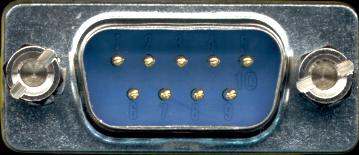
PC Com Port - EIA-574
RS-232 pin out DB-9 pin used for Asynchronous Data